Original Link: https://www.anandtech.com/show/6786/gigabyte-z77xup7-review-oc-oriented-orange-overkill
Gigabyte Z77X-UP7 Review: OC Oriented Orange Overkill
by Ian Cutress on March 1, 2013 10:30 AM EST- Posted in
- Intel
- Gigabyte
- Motherboards
- Z77
Aside from Gigabyte’s gaming motherboards (the G1 Series) and its channel motherboards (such as theUP4 TH, MX-D3H), there exists the OC Oriented series of motherboards. The first participant in this specific range was the X58A-OC, a stripped down LGA1366 motherboard for Gulftown CPUs to focus on the top overclocking scores with up to 4-way GPU action. The latest in the line is the Z77X-UP7, a strike at the heart of Sandy Bridge and Ivy Bridge CPUs, which we are testing today. With a fuller feature set than the X58A-OC, our black and orange UP7 is designed to take world records by extreme overclockers, while perhaps still being a motherboard for the high end enthusiast with a deep wallet.
Overclocking for Z77 – Why Focus on Extreme Overclockers?
The motherboard market shrank in 2012, with reports suggesting that from the 80 million motherboards sold in 2011, this was down to 77 million worldwide in 2012. In order to get market share, each company had to take it from someone else, or find a new niche in an already swollen industry. To this extent, after the success of the ROG range, the top four motherboard manufacturers now all have weapons when it comes to hitting the enthusiast or power user with an overclocking platform. These weapons are (with prices correct as of 2/13):
$400 – Gigabyte Z77X-UP7
$369 – ASUS Maximus V Extreme
$270 – ASUS Maximus V Formula
$230 – ASRock Z77 OC Formula (our review)
$200 – MSI Z77 MPower (our review)
$200 – ASUS Maximus V Gene
There are two main differentiators between the low (<$270) and the high (>$350) end. The first is usually the choice to include a PLX PEX 8747 chip to allow 3-way or 4-way GPU setups. We covered how the PLX chip works in our 4-board review here, but to summarize, this functionality can add $30-$80 onto the board depending on the bulk purchase order of the manufacturer and the profit margins wanted. The second is usually attributed to the functionality and power delivery – the 32x IR3550s used on the Gigabyte Z77X-UP7 costs them a pretty penny, and the extensive feature list of the ASUS ROG boards usually filters through.
In the past there have been attempts at pure overclocking boards, such as the Gigabyte X58A-OC, which was entirely stripped of all but the necessary components for pushing overclocks under sub-zero conditions for competitions. The board itself was cheaper due to the functionality not present, but it did not provide a rock solid home system for many users. The ASUS ROG range, as we reviewed in 2012, has been releasing motherboards for both gaming and overclocking for several years, trying (and succeeding) with the mATX Gene, ATX Formula and Extreme. All three of these boards continuously push both the gaming and OC frontiers, with a slight gaming focus on the Formula and an OC focus on the Extreme, but all boards cross over into each other’s territory very easily.
For the purposes of this review, it should be noted that one philosophy at Gigabyte (and ASUS) is to help supply the enthusiast with information. For any component company (CPUs, GPUs, motherboards, audio, storage) there will be users who are enthusiastic about the products that the company produces, and many active online forums will have various advocates for each company (as well as various detractors). If these particular power users on the forums enjoy using their products, then they will advise regular users, and sales may filter through. In order to help this, Gigabyte (and other companies) have cultivated relationships with several of these power users, and are giving them support such that they can aid and answer the questions on the forums better, or produce review content as products go on sale. It helps also that some of them are talking direct with Gigabyte on support issues or design feedback from the forums. As mentioned, this strategy has potential, as long as the aficionados do not corrode their own integrity in public verbal wars (which may happen in debates on The Internet™) or are labeled by the enthusiast community as a wielder of immediate bias. This philosophy has good intentions on all sides – it is a primary benefit for these companies to have voices within active communities, as these are the enthusiasts that will influence the regular users down the chain. The additional downside to this strategy is being able to track quantitatively the benefits to the company and to sales. If an executive or power user does not understand the situation in its entirety, and there are no hard numbers to back up the policy for internal reports, it could be dropped in times of austerity or reorganization.
The Z77X-UP7 lands dead center inside the enthusiast/power-user/overclocker arena, and makes a big dent. The only question is if it makes any shockwaves in terms of gaming or regular users. On the face of the specification sheet, I would say no – a user would have to want 5 GHz from an extreme Ivy Bridge water cooling setup as well as 3+ GPU capability to consider the Z77X-UP7. For all other usage scenarios, Gigabyte has users well covered – the G1.Sniper 3 for gamers, the Z77X-UD5H for power users, or the Z77X-UP4 TH for Thunderbolt users. In my analysis, the Z77X-UP7 is the best example of the word niche, for motherboards, I have encountered on the Z77 platform.
Gigabyte Z77X-UP7 Overview
I am not going to sugar coat it - $400 is a lot of money for anyone to spend on a motherboard, especially when the most expensive retail CPU (non-Xeon) that you can buy is only $320. For $400, stability, feature set and a sense of achievement are needed up and down the product. We criticized the $450 ASUS P8Z77-V Premium for offering too much functionality for an individual consumer and the Gigabyte Z77X-UP7 is surreptitiously straddling that borderline.
The title of this review is ‘OC Oriented Orange Overkill’. One feature in particular on the Z77X-UP7 is mildly described as ‘overkill’ – the power delivery. Since Computex 2012, Gigabyte have been getting to grips with International Rectifier’s IR3550 60A PowIRstage, a high efficiency, small footprint power delivery IC designed to supply power and produce less heat while doing it. The IR3550 is not a cheap IC, with IR’s own website quoting $2.65 each when purchased in units of 10k, meaning ‘~$3.20’ each when on a motherboard. Gigabyte decide to use 32 of them on the Z77X-UP7 (~$100, or 1/4 of the overall price), and are often showcasing up to 2000W of deliverable power through the platform. This is despite an i7-3770K requiring <100W at stock, ~250W at 5 GHz and ~600W on crazy 6.8 GHz liquid nitrogen overclock scores. Having 32 IR3550s on the board is complete overkill – no extreme enthusiast power user will ever need to come close to half the 2000W of deliverable power. We are reminded the analogy of power supplies and cars – going everywhere at 70 mph in an old Fiat Panda that has 80 mph max speed can be frustrating, but using a 160 mph Porsche to cruise at 70 mph is relatively comfortable. While the analogy is a bit of a stretch on the power delivery, the IR3550s should definitely run cool, even at 5 GHz for a daily build, and is akin to swatting a fly with a Buick for high overclocks, but there is a price in that privilege.
The Z77X-UP7 is also very orange. The importance of color coordination on the high end motherboards is essential, both in terms of the motherboard manufacturer promoting the product, and the end users that like to show it off in theme builds or overclocking contests. So we get the custom heatsinks, the PCIe slots and memory slots to match, and everything else is black (apart from all the white surrounding every onboard component). In my opinion the orange works well, though it will be hard to see in a gaming case using >3 PCIe devices and a full array of memory – perhaps some orange strip LED additions along the heatsink would not be too out of place. Even with the orange, an overclocker will full insulation can easily hide any trace of the hardware they are using, making the styling void:
K404 from Team GB Overclockers breaking the record for 3xGTS250 using a Z77X-UP7 and an i7-3770K at 5938 MHz, all under Liquid Nitrogen, at a 2012 UK OC event
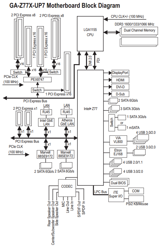
Another main feature from the UP7 is to do with the PCIe slots – the price of the Z77X-UP7 puts it squarely in the ‘boards with PLX8747 chips’ bracket. We covered several Z77 motherboards with this PLX8747 chip, which enables the Z77 platform to have up to 4-way GPU functionality on board at more than x8/x4/x4 allocations (click here for our detailed explanation on how the chip works). There are many ways to splice how the PLX8747 operates, as it introduces a minor % overhead on frame rates compared to native setups. Gigabyte have kept it simple and oriented the board such that when a single PCIe device is in use, the black PCIe slot bypasses the PLX chip for default and no overhead running at PCIe 3.0 x16. When more than one device is needed, the orange slots split into x16/-/x16/-, x8/x8/x16/- or x8/x8/x8/x8 as required. The chipset diagram in the manual explains it best, although we have our own diagram later in the review. We initially estimated the cost of this chip around $80, though sources suggest that <$40 is a more reasonable figure.
Even if we generously partition off the power delivery and PLX chip as a $175 of the motherboard cost to manufacture combined, that leaves $225 still to go. The Z77X-UP7 is aimed at extreme overclockers first, a stable multi-GPU platform second, with gamers and others being the after thought. With that in mind, our overclocking features include onboard buttons (‘OC Touch’) to manipulate both the CPU multiplier ratio and the BCLK on-the-fly. We also have voltage read points, with included cables to make connections easier, as well as power/reset buttons, an LN2 switch, a two-digit debug and DualBIOS in case of BIOS corruption.
For non-overclock related hardware, users get a total of 10 SATA ports, such that there are four SATA 3 Gbps and two SATA 6 Gbps from the chipset, with another four SATA 6 Gbps coming from a pair of Marvell 88SE9172 controllers. There is an onboard mSATA port, although it shares bandwidth with one of the SATA 3 Gbps ports. USB 3.0 comes in thick on the UP7, with four ports from the chipset split between a header and the rear IO, four more ports on the rear IO from a VIA VL800, and another onboard header powered by an Etron EJ168 chip, making 10 in total. We also get seven fan headers on board to play with.
Despite the UP7 being a board for GPU users, Gigabyte went with the full array of video outputs (VGA/DVI-D/HDMI/DP), rather than filtering them down and adding in USB 2.0 ports. The two GbE NICs on board are a single Intel and a single Atheros implementation, though no Killer NICs as seen on the G1 series, despite the price. Whereas ASUS have an add-in card for the IO plane with a BT/WiFi module in order to free up PCIe space, Gigabyte have to include a PCIe x1 card in the box to match up. The Gigabyte GC-WB300D card included in the box is a 2x2:2 802.11 a/b/g/n implementation for dual band (2.4 GHz and 5 GHz) as well as Bluetooth 4.0. The ASUS implementation in this regard is more ideal, especially when video outputs are not completely necessary on a board like this.
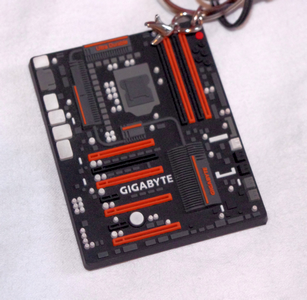
For $400, there are a lot of goodies in the box inter alia a USB 3.0 front panel, the afore mentioned GC-WB300D WiFi/BT card, a handful of SATA cables, and an eSATA back plate. Unfortunately there is nothing specific to the UP7, nothing orange and Z77X-UP7 branded, such as the SLI bridges or a small gimmicky addition, such as the Z77X-UP7 key chains being handed out at Gigabyte sponsored events:
While the motherboard and the box is UP7 styled, the BIOS and software are straight from the main channel products. Our old punching bag ‘3D BIOS’ is out for another spin, which still is not a perfectly smooth experience, and we experienced some minor glitches during our overclocking tests when the CPU voltage was too low. We should point out that Gigabyte has been extensively working on pushing the high-end memory kit compatibility for memory overclockers, similar to ASUS. The software on the UP7 is in need of a pick-me-up, with EasyTune needing an update soon. There is no UP7 specific software features (desktop backgrounds, Windows themes), which is a shame.
As with all Gigabyte Z77 motherboards, the Z77X-UP7 implements MultiCore Turbo when XMP is enabled, giving some extra MHz at stock under constant loading. Interestingly Gigabyte did not implement MCT-Plus on the UP7 like on the G1.Sniper 3, and as such did not give it an extra multiplier across the board at stock. This board is designed to be overclocked, so MCT is a minor feature, but our testing suggested that the efficiency of the Z77X-UP7 is in the top 3 out of the Z77 MCT motherboards we have tested.
Overclocking on the Z77X-UP7 was a little up and down in all honesty – the automatic overclock settings are only in the OS software, and the top auto overclock ran quite hot during our OCCT test. A small issue with ET6 means that if you save an OC profile but clear the BIOS, ET6 will still load your overclock on the next OS boot, implementing BCLK adjustments in the BIOS itself. For manual overclocking, the BIOS options are a little annoying, with the important data always in a different menu to the rest of the settings. It took slightly more voltage to hit various speeds than the MSI Z77 MPower and the ASRock Z77 OC Formula at the low end, but as we passed 4.9 GHz, the voltages matched up.

Our minor testing issue with the board was more down to GPU drivers than anything else. As part of our normal testing routine our AMD games tests are done with Catalyst 12.3 drivers. When using these in a 3-way or 4-way GPU setting, the orange PCIe slots that max out at PCIe 3.0 x8 would boot and run a game at x8, but reduce to PCIe 3.0 x1 after the GPUs enter an Ultra Low Power State. When waking the GPUs, they would spin up but any attempt to stress them would cause a blue screen. We eventually got some 4-way results to compare to results on other motherboards (which do not have this problem) after testing two different boards, but both had the same issue. After double testing it was not the fault of the GPUs, or the memory, or the motherboard, or the power supply, the issue was strangely resolved after updating the drivers to Catalyst 13.1. Speaking to Gigabyte gave the simple answer – some sets of AMD drivers work and some do not. Specifically 12.3 and 12.6 do not, but 12.4 and 13.1 do. This is an odd circumstance to be in, especially if the better drivers end up being the ones that cause the system to crash in the future.
Overall, the Z77X-UP7 is a tough sell to most users. $400 is a lot of money to put down on a motherboard, especially if it does not have Thunderbolt, built-in WiFi, a better than Realtek audio codec, and the software/BIOS needs some work. For overclockers, the voltage read points and auto-OC buttons are great, and the IR3550 power delivery should be able to cope with anything you throw at it. But strip that all way and we are left with a G1.Sniper 3 under the hood with minor changes. Comparing the G1.Sniper 3 to the UP7 (minus IR3550s) gives the G1 a Killer NIC, better audio, TPM, a PCI slot and better stock speed, but the UP7 has a single PCIe bypassing the PLX, OC Touch, more fan headers and separate BIOS switches. This makes the G1.Sniper 3 the choice for gamers, and the Z77X-UP7 the choice for overclockers that want on-the-fly adjustments.
Gigabyte Z77X-UP7 Visual Inspection
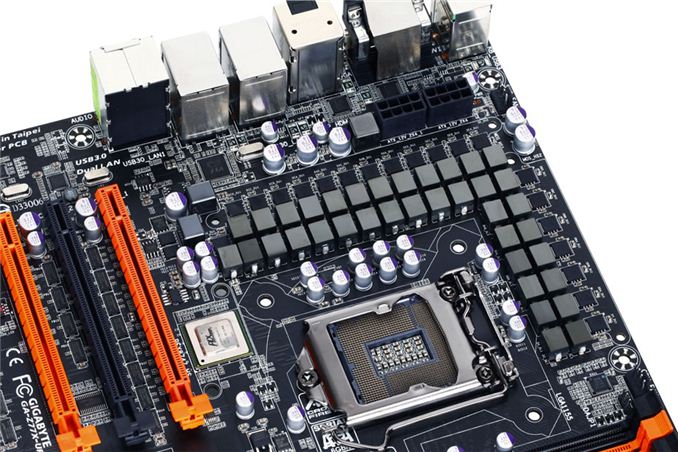
In order to fit the 32 IR3550s onto the Z77X-UP7, as well as the mSATA, OC-Touch buttons, voltage check points and headers, the motherboard is an extra inch wider than standard ATX, also known as E-ATX (305mm x 264mm). The socket area has plenty of space around it for large heatsinks due to the power delivery heatsink being placed slightly further back than usual due to the IR3550s. The 32 phase arrangement is designed in a custom 8x4 rather than 8x2x2, meaning that at any one time 8 phases are operational. It loops around in four cycles to use all 32, 8 at a time, but can use all 32 at once if needed such as for the 2000W power test. This is nothing new in terms of high end power delivery, though 8x2x2 is more common with phases spending one cycle on, one cycle off, rather than one cycle on, three cycles off.
For fan headers, the socket has access to three in immediate reach – a 4-pin CPU fan header above the socket to the right, a 4-pin SYS header above the two 8-pin CPU power connectors on the top left, and a 4-pin SYS fan header between the memory slots and the 24-pin power connector. The other four fan headers are found on the bottom of the board: two 3-pin and two 4-pin, all SYS headers. Ideally I would have liked another CPU header, or one of the bottom headers moved more to the top of the board – for both regular usage and overclocking.
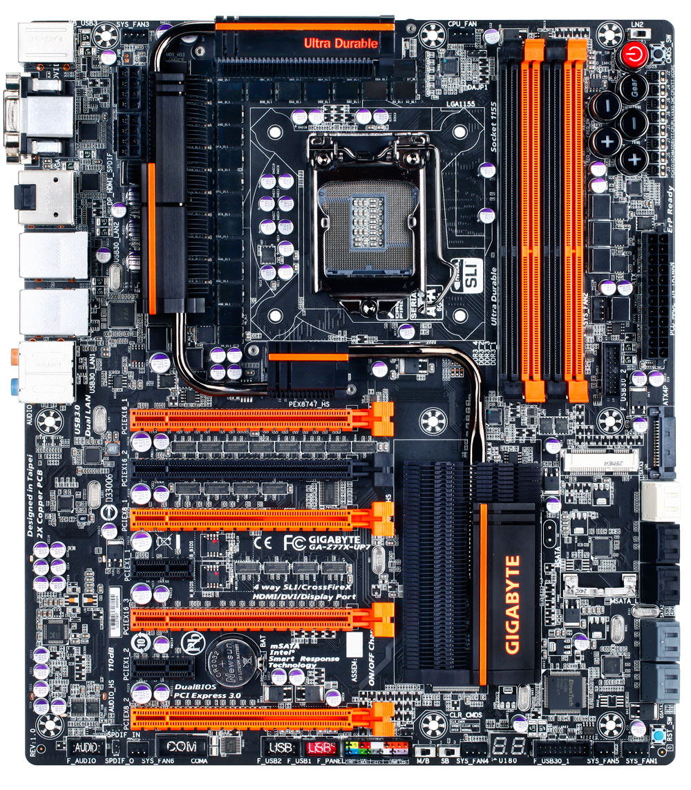
The power delivery heatsink is a vast extended black and orange affair, moving through the phases and VRMs, connected via heatpipe over a PLX 8747 chip and down to the chipset. The PLX chip and chipset come in at ~16W together, although there are very few circumstances that would be taxing both the PCIe lanes and IO (video encoding and file transfer perhaps) at the same time. The heatsink is custom made for the UP7, such that the fins are thin and there are plenty of them, maximizing surface area for airflow in case of large bulky devices (4-way GPUs, LN2 pots) being used. A minor criticism is that when performing sub-zero overclocking, the cold likes to spread around the board, causing more areas for condensation to occur (meaning that good insulation is very important). With a large surface heatsink such as this, it gives plenty of surfaces for condensation to form, and that condensation could roll off of the heatsink onto the motherboard. With that being said, I have not heard of it being an issue so far, but it is theoretically an issue.
Unlike any other Z77 motherboard we have tested at AnandTech, I believe this is the first one on the test bed with two 8-pin power connectors for the CPU. Typically we have a single 8-pin, or an 8-pin and a 4-pin, and the mITX models using a single 4-pin. Sandy Bridge-E requires two 8-pin connectors when pushing the overclocks, but the main reason for the two 8-pins on the UP7 is presumably to cater for the 32 phase power delivery. The board also has a SATA power connector, to give extra juice to the PCIe slots – the PCIe specification says that each slot should provide 75W, however asking for a stable 300W supply from the 24-pin ATX power connector is perhaps asking a little too much. In our testing, to use any of the orange PCIe slots, the SATA power connector had to be used.
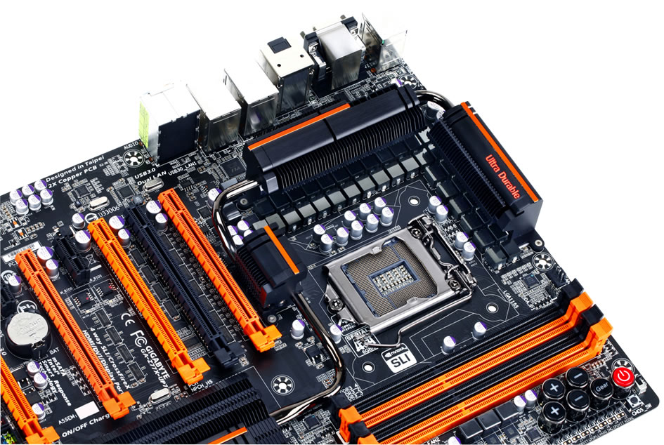
Moving clockwise around the board from the chipset, we have our top right corner full of overclocking utilities. The big red button is a standard Gigabyte power button that distinguishes itself from the ClearCMOS button next to it in both size and visuals such that it is hard to press the wrong one, unlike on some other motherboards. Above the power button is an LN2 mode switch that drops the CPU multiplier down to 16x, ensuring that opening verification programs like CPU-Z does not cause the system to crash.
Below these are a set of five ‘OC-Touch’ buttons, designed to help the user overclock on-the-fly. This allows extreme overclockers to increase the CPU speed during non-CPU intensive tasks, like GPU tests, and reduce it during CPU tasks. The top plus and minus buttons change the CPU ratio, adjusting it by +1 or -1 when pressed. The bottom two buttons change BCLK by 1 MHz, and when the ‘Gear’ button is activated, the buttons adjust BCLK by 0.1 MHz. Unfortunately the bottom row of three buttons do not work out of the box – they only work in the OS and when the OC-Touch driver is installed. Below the OC-Touch buttons are the voltage check points. Users can either directly attach the connections to their multi-meters, or use the plastic adapters supplied in the motherboard box. Each check point comes with its own ground, and all the major voltages are covered – VCore, VTT, IMC, PLL, VDIMM, PCHIO and so on.
Down the right hand side below the OC-Touch is our 24-pin ATX power connector, flanked by a 4-pin fan header, a USB 3.0 header (from the chipset) and a SATA power connector for the VGA ports. The SATA power connector sits above the SATA ports, where we have access to 10 in total – two SATA 6 Gbps and four SATA 3 Gbps from the chipset, then four SATA 6 Gbps from Marvell 9172 controllers. Beside these is an mSATA port, but it shares bandwidth with one of the SATA 3 Gbps, meaning a choice between a SATA port and an mSATA. Each of the chipset ports are RAID 0, 1, 5 and 10 capable, whereas the Marvell SATA ports are only RAID 0 and 1.
Along the bottom of the motherboard, from right to left, the system provides a reset button, two fan headers, a USB 3.0 header powered by an Etron EJ168 controller, a two-digit debug LED, another header, then two BIOS switches. These switches deal with the DualBIOS system – one switch selects either BIOS one or two, while the other enables and disables BIOS recovery. The latter can be important when overclocking, should the motherboard want to initiate BIOS recovery after several failed overclock attempts but the user wants to tweak the settings more. Moving along the left of the board form the switches is the front panel header, two USB 2.0 headers (one of which supports QuickCharge), a COM header, a final fan header, and front panel audio powered by a Realtek ALC898. Two points are worth noting – this is the first Gigabyte motherboard in a while I have seen without a TPM header, and the Realtek ALC898 is a dichotomous choice of codec on a $400 motherboard. On the one hand to appeal to anyone other than overclockers, getting something better on board would be a good selling point given the price bracket, whereas overclockers would prefer it removed altogether.
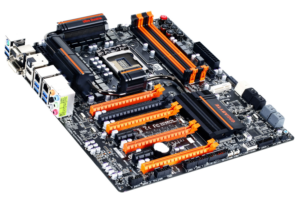
In the overview to this review I remarked on the PCIe configuration being something slightly different. We have a system that uses a PLX 8747 chip to output 32 PCIe 3.0 lanes to any number of PCIe slots, while taking in either 8 or 16 PCIe 3.0 lanes from the CPU. We have seen both examples in our four-board PLX 8747 review back in August 2012. Ideally we do not want the chip as it adds some extra overhead – we would rather have the lanes straight from the CPU itself. But the Z77 specifications only allow up to an x8/x4/x4 distribution of the 16 CPU lanes, which potentially limits bandwidth and denies 4-way PCIe setups. With the PLX, we can do a full PLX setup (x8/x8/x8/x8), or only send 8 lanes to the PLX and keep 8 lanes for the first PCIe slot (giving x16/x8/x8/x8) but limiting GPUs 2, 3 and 4 in upload bandwidth. Gigabyte instead use switches to send the PCIe lanes around – when one GPU is being used, put it in the black slot for x16 PCIe 3.0 from the CPU, bypassing the PLX chip. When we use more GPUs, the orange slots have to be used, which have a full PLX layout (up to x8/x8/x8/x8). In crude MSPaint notation:
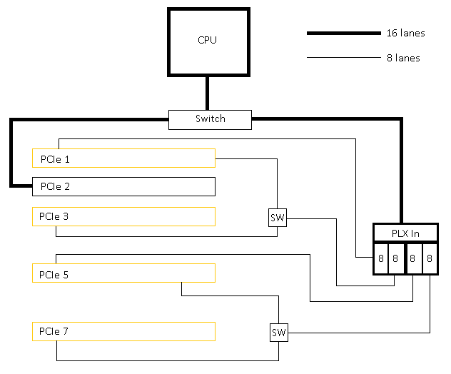
Starting at the CPU, it sends 16 PCIe lanes down to a switch – the lanes can either all go to PCIe 2 for optimal single GPU performance, or to the PLX chip for multi-GPU layouts. When at the PLX chip, we get 32 lanes to play with (see our original PLX 8747 review for reasons why), which are all sent out in sets of eight. Set 1 goes to PCIe 1 and Set 3 goes to PCIe 5. Set 2 encounters a switch – if there is a device in PCIe 3, it goes there, otherwise to PCIe 1. Set 4 does likewise – if there is a device in PCIe 7, it goes there, otherwise to PCIe 5. Sounds complicated, but it allows for the best lane allocation for up to four devices.
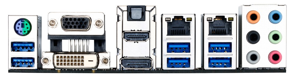
The rear IO is a little odd, considering the market segment for the UP7. The motherboard is built for multi-GPU setups, and thus it makes little sense to include every video output the integrated GPU offers. The sole explanation I could suggest would be that Gigabyte could not route any more USB 2.0 ports up to the rear IO without adding extra PCB layers or compromising speed. Nevertheless, I would imagine the video outputs rarely being used except for quick testing. From left to right, we get a combination PS/2 port, two USB 3.0 (VIA), D-Sub, DVI-D, HDMI, DisplayPort, optical SPDIF output, two gigabit Ethernet ports (one Intel, one Atheros), two more USB 3.0 from VIA, two USB 3.0 from the chipset, and audio ports. Note that in the manual, it states the first two USB 3.0 ports (left to right) are from the chipset – this is wrong and it is the two USB 3.0 ports on the right. Place your keyboard and mouse here to avoid driver issues before installing the VIA USB 3.0 drivers.
Board Features
| Gigabyte Z77X-UP7 | |
| Price | Link |
| Size | E-ATX (305mm x 264mm) |
| CPU Interface | LGA-1155 |
| Chipset | Intel Z77 |
| Memory Slots |
Four DDR3 DIMM slots supporting up to 32 GB Up to Dual Channel, 1066-2800 MHz |
| Video Outputs |
D-Sub DVI-D HDMI DisplayPort |
| Onboard LAN |
Intel 82579V Atheros AR8161/8165 GC-WB300D Dual Band 802.11b/g/n WiFi PCIe x1 Card |
| Onboard Audio | Realtek ALC898 |
| Expansion Slots |
1 x PCIe 3.0 x16 4 x PCIe 3.0 x16 via PLX 8747 - x16/-/x16x/- - x8/x8/x16/- - x8/x8/x8/x8 2 x PCIe 2.0 x1 |
| Onboard SATA/RAID |
2 x SATA 6 Gbps (Chipset), RAID 0, 1, 5, 10 4 x SATA 3 Gbps (Chipset), RAID 0, 1, 5, 10 4 x SATA 6 Gbps (Marvell 8172), RAID 0, 1 1 x mSATA 3 Gbps (Chipset, shares with SATA port) |
| USB |
4 x USB 3.0 (Chipset) [2 onboard, 2 rear panel] 4 x USB 3.0 (VIA VL800) [4 rear panel] 2 x USB 3.0 (Etron EJ168) [2 onboard] 4 x USB 2.0 (Chipset) [4 onboard] |
| Onboard |
6 x SATA 6 Gbps 4 x SATA 3 Gbps 1 x mSATA 3 Gbps 2 x USB 3.0 Headers 2 x USB 2.0 Headers 7 x Fan Headers 1 x Front Panel Audio Header 1 x Front Panel Header 1 x COM Header Power/Reset/ClearCMOS Buttons Two Digit Debug OC Touch Buttons Voltage Measurement Points BIOS Switches LN2 Switch |
| Power Connectors |
1 x 24-pin ATX Power Connector 2 x 8-pin CPU Power Connector 1 x SATA Power Connector for VGA |
| Fan Headers |
1 x CPU (4-pin) 6 x SYS (4x4-pin, 2x3-pin) |
| IO Panel |
1 x Combination PS/2 Port 4 x USB 3.0 (VIA) D-Sub DVI-D HDMI DisplayPort Optical SPDIF Output 2 x GbE NIC (Intel, Atheros) 2 x USB 3.0 (Chipset) Audio Jacks |
| Warranty Period | 3 Years |
| Product Page | Link |
Aside from the power delivery, the main competition the Z77X-UP7 has is with the G1.Sniper 3. The UP7 gets the overclocking features, such as OC Touch, the single PCIe slot not attached to the PLX and fan headers, whereas the G1. Sniper3 has Core3D Audio, a Killer NIC, TPM and a PCI slot. The rest of the package is much the same, although there are no UP7 specific add-ons, like with ASRock Z77 OC Formula which included some standoffs for overclocking and a themed back to keep all the bits in.
If we compare to the Z77 OC Formula, the Z77X-UP7 has more NICs, an mSATA port, 4-way GPU support, more IGP video outputs, a bundled WiFi card, two more USB 3.0 ports (at the expense of 6 USB 2.0 ports), an LN2 switch and the CPU power delivery (not to mention the additional VGA comes from a SATA port rather than a molex). On the other hand, the Z77 OC Formula has a combo air/water VRM heatsink, PCIe switches, more USB ports on the rear IO, one more fan header than the UP7 (even though it is occupied), and a selection of BIOS/software that is miles easier to use (more on that later).
Gigabyte Z77X-UP7 BIOS
When a motherboard manufacturer develops a range of products, most of who I am expects to see some form of product segmentation when it comes to interaction with the motherboard beyond hardware. With the ASUS ROG range and Fatal1ty by ASRock, our BIOS and software both get new skins, even if there is not anything fundamentally different in the software itself. Both ASUS and ASRock have the benefits of easy and understandable systems to work with, but in the past Gigabyte has not had the luxury. Perhaps this is partly why the Z77X-UP7 BIOS (and software) uses the same old systems we have reviewed before – there is more worth in diversifying something good than partitioning out the average, especially when the competition is highly competitive.
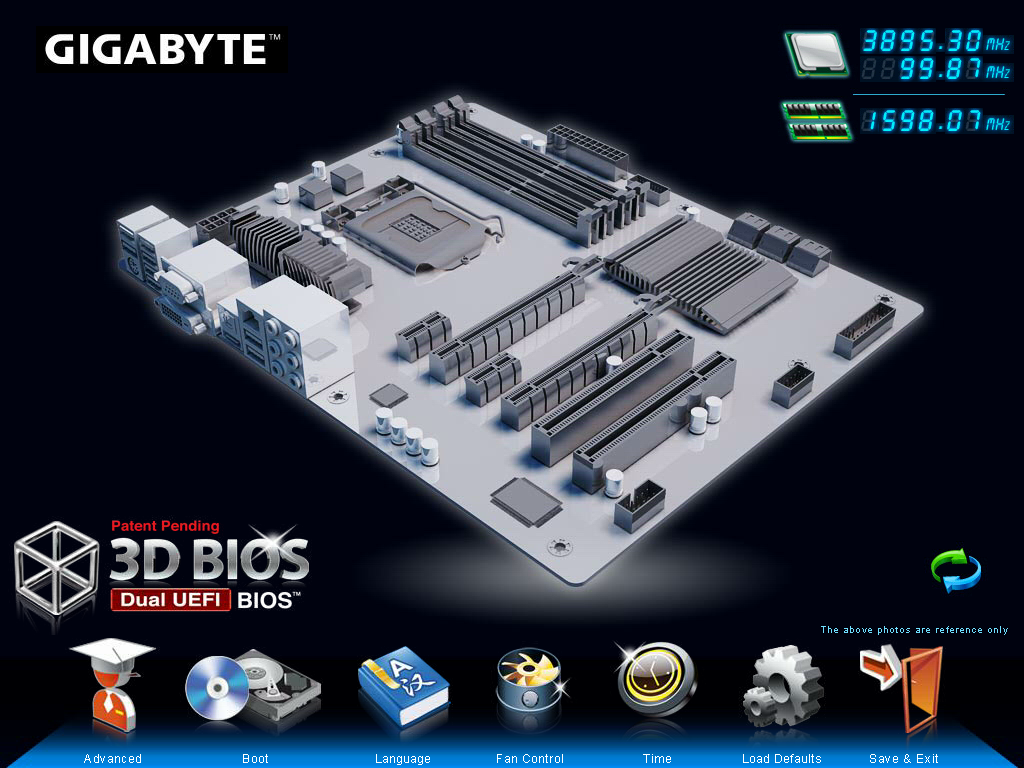
So for the Gigabyte Z77X-UP7, our mainstay in the BIOS is the ‘3D BIOS’ representation. In previous reviews we have labeled this as near to a mild gimmick as you can get – an oblique image of Generic Motherboard #234, with various parts of the board that can be highlighted. If the user has no knowledge of what a motherboard looks like, this means nothing, as there are no tool-tip popups when the SATA or PCIe are selected, or any indication of what a BIOS is for. We have no indication of what motherboard is actually being used, what BIOS revision is installed, what CPU is installed, how much memory is installed, or any vital temperature/voltage/fan values. While I understand the split between using the BIOS as a marketing tool for the system (as most vendors do) compared to using the BIOS as a marketing tool for the motherboard (Gigabyte), this is an odd and frankly bad way of going about it. I cannot tell a family member down the phone to select the memory slots for XMP if they do not know what memory slots look like and there is nothing to guide them there. I impatiently wait for an updated version of this front screen geared towards a more user friendly experience and full of informative data on the system.
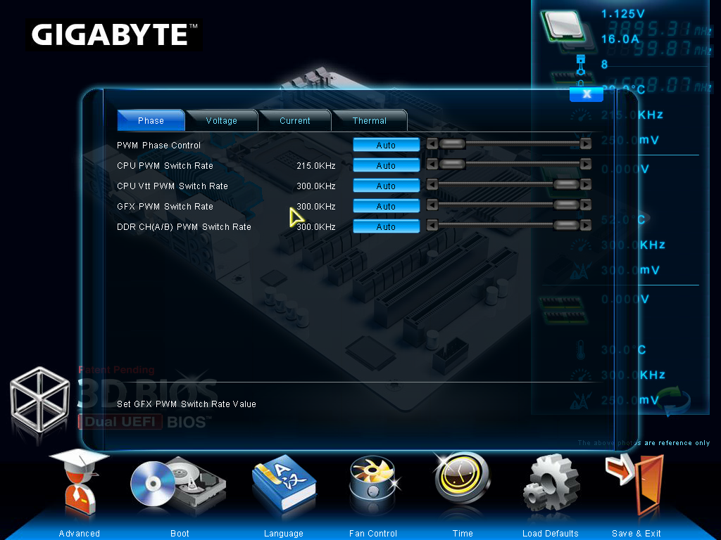
Rants aside, functionality wise each part of the motherboard does display a few options. The CPU options involve frequency and voltage adjustments with a section for memory, the SATA options allow changing of the controller mode (AHCI as default, but also IDE and RAID), and the rear IO deals with enabling/disabling controllers along with USB functionality. The power delivery sub-menu offers phase control, as well as various voltage, current and thermal options. Most of these sub-menus are merely the same as their ‘advanced’ menu counterparts but with sliders where appropriate.
In this front screen we also get icons on the bottom to adjust the boot order, the language of the BIOS, and our basic fan controls. Over the past couple of years the Gigabyte fan controls have spanned a small range from a confusing mash of odd value assignments to basic gradient application. Despite the numerate fan headers on board, only the 4-pin ones are controllable, and Gigabyte will give you access to that gradient in odd units known as PWM value/°C.

For the non-engineers, the higher the number of this option will result in the fans receiving more power at lower CPU temperatures (i.e. a more aggressive fan control). This is despite the fact that a fan speed profile is never linear, shown by my CPU fan:
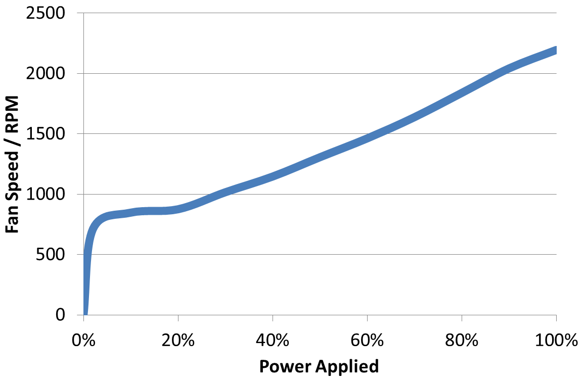
Below 5% power, my fan is essentially off. From 5-20%, the fan spins at 800 RPM regardless of how much power is applied. Above this the RPM to Power ratio is fairly constant. What motherboard manufacturers should be doing (ASUS do this in software, Biostar do it in the BIOS) is giving an option for a fan test, polling this data, and then adjusting the fan profiles via software to match. A common response is that ‘it’s more complex than you think’ or ‘it’s too complex’ – when dealing with two inputs (CPU temperature, fan speed) and one output (power applied), writing black box software to connect them in various ways should be a stroll in the park for any trained programmer.
Second rant aside, the bulk of the BIOS is actually a lot more readable in the Advanced menu (icon on the bottom left). Opening this takes us straight into the M.I.T. (Motherboard Intelligent Tweaker) tab, which offers some of the information we should have had before – BIOS version, CPU temperature, VCore. It is still missing the words ‘Gigabyte Z77X-UP7’ and ‘i7-3770K installed’ however.
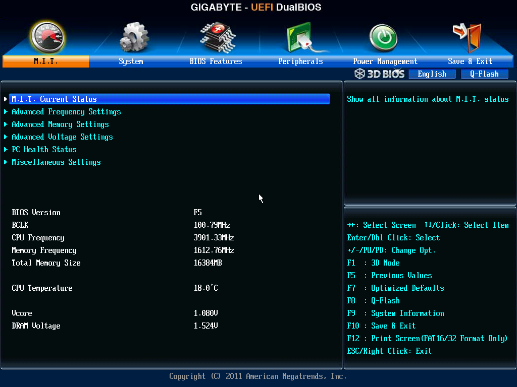
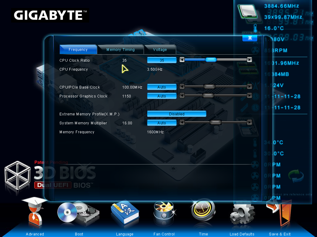
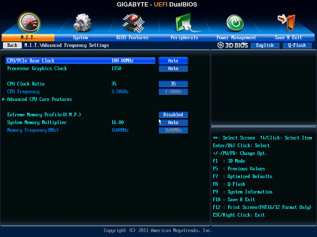
The MIT tab gives sub menus for a current status screen, frequency settings, memory settings, voltage settings, PC Health (i.e. fans) and a couple of other miscellaneous options. The frequency settings menu is where most overclockers will head, and the basic options to adjust multiplier, base clock and memory are here, with power options in a sub-menu off of this one. What are not here are the voltage options. I had a brief argument with HiCookie, Gigabyte’s in-house overclocker, the last time I met him about why this is the case. Personally, when overclocking the CPU, I want all my CPU options in a single menu – multiplier, BCLK, power options, voltages and temperature readings. In HiCookie’s experience, he wants everything in separate menus – when he wants to change a voltage, he wants a menu with all the voltage options. I can see how doing it that way may help such that users do not accidentally pump 2.0 volts through their new CPU, but the only users in this menu would be the enthusiasts. Perhaps we can have both - keep the separate menus for 3D BIOS mode, and give me one page for the CPU options including voltages and temperature sensors, and another for memory settings too.
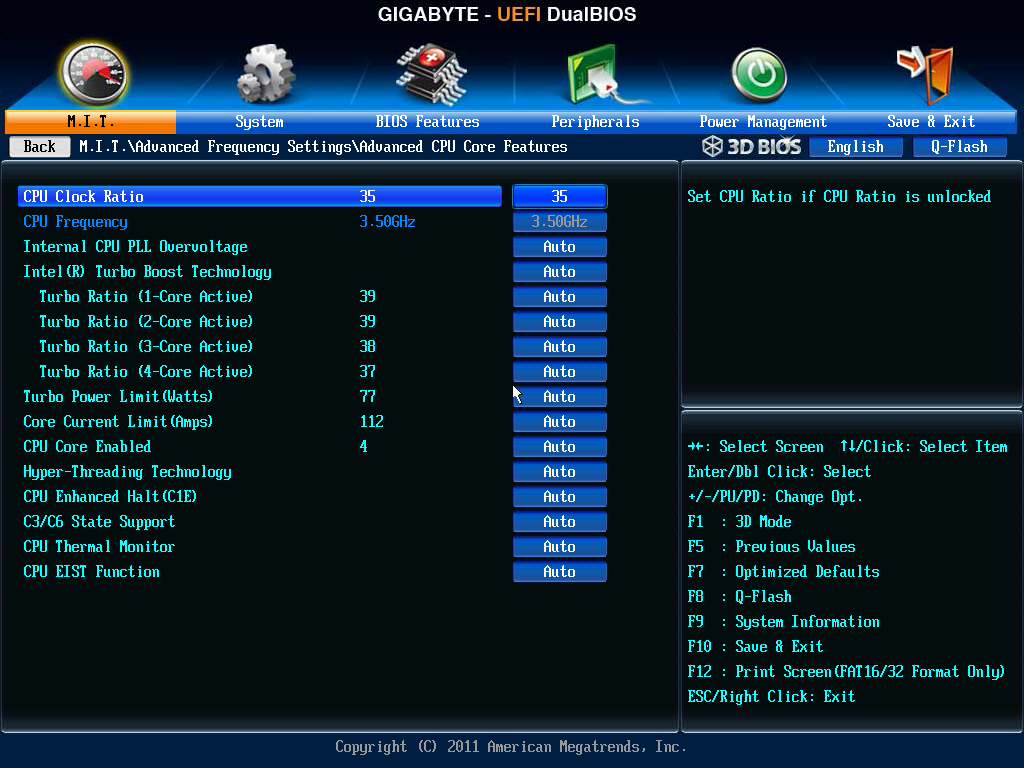
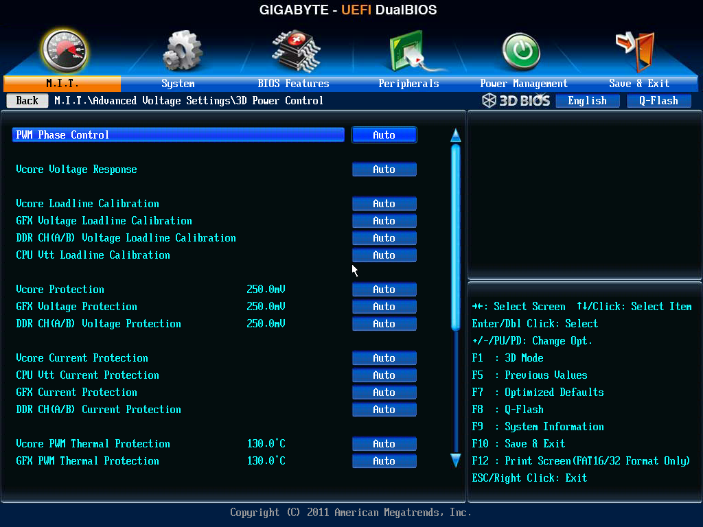
The 3D Power options are fairly substantial, allowing the user to adjust thermal protection limits, switching rates, over current protection and over voltage protection. However it still seems odd that Gigabyte have split almost everything into separate menus. For example, when dealing with just the voltages, the CPU options and memory options are in separate menus. Doubly worrying is that although Gigabyte has left a space on the top right as a description box for the option selected, the descriptions are short or either non-existent.
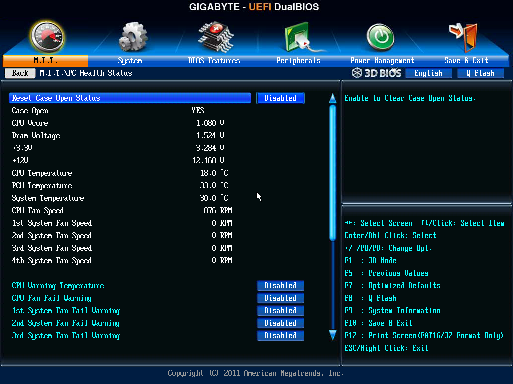
The fan options are in the MIT->PC Health menu, where we get most of the sensor readings – some voltages, onboard temperatures and fan speeds. By default all the warnings the board can provide (fan fails and CPU temperatures) are disabled, and our fan options are just as limited as in 3D BIOS mode.
Oddly enough Gigabyte does not allow direct control over the PCIe lane allocation. In most high-end motherboards, we are able to select individually which of the PCIe slots are to be PCIe 3.0 enabled, and drop them down to PCIe 2.0/1.1 if compatibility is an issue. On the Z77X-UP7, we only get a single option to control all PCIe slots – ‘PEG Gen3 Slot Configuration’, in the MIT->Miscellaneous menu.
Other options in the BIOS are as regular as any other system – boot order, controller functionality, Smart Connect Technology, Rapid Start Technology and SATA modes. The UP7 also has a segment in the BIOS features menu for Windows 8 quick POSTing, under CSM Support. Ideally this should be wrapped up into an easier set of options to make it easier to understand – not everyone knows that under Windows 8 these should be adjusted for those quick POST times. A final positive note is that Gigabyte includes Boot Override, an option for a single time boot from a specified device – very handy when installing an OS via USB.


Gigabyte Z77X-UP7 Software
As mentioned in the BIOS section, on the high end segments for motherboards often the manufacturer will partition the top range with new features or a new look. Gigabyte for the most part has not done this specifically with the UP7 – the usual gamut of EasyTune6 and 3DPower are here in their original form, as well as some of the newer Gigabyte software utilities such as USB Blocker and TweakLauncher. The only ‘new’ skin comes with the Gigabyte branded version of CPU-Z, the system identification tool used by overclockers to verify and confirm the hardware they are using to others. The CPU-Z skin is an ‘OC Oriented’ feel for the G1 range as well, rather than something orange and shouty for the UP7.
First up is the driver CD itself, which is still the same design layout as far back as P67 at least:
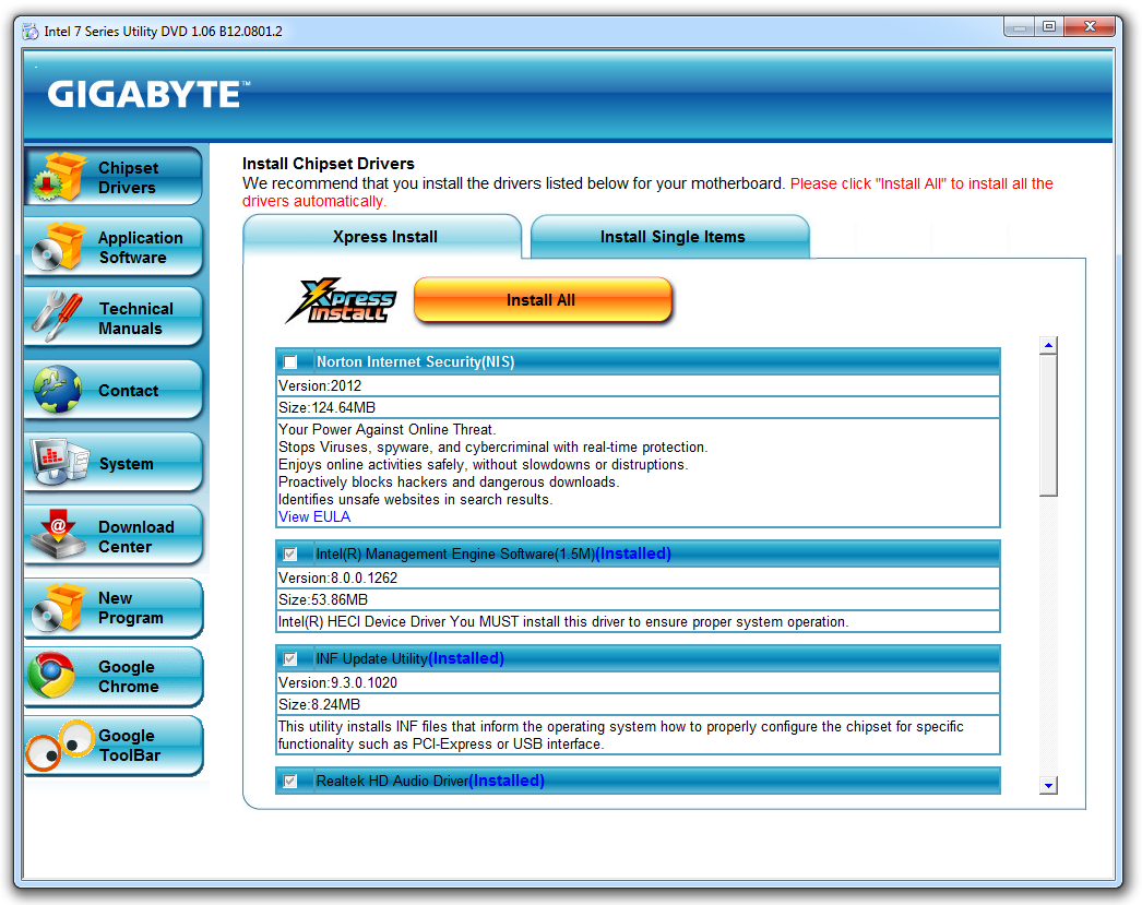
The disk first shows a list of ‘Chipset Drivers’ from which the user can install all at once, or deselect the ones not needed. Notice in the screenshot above that ‘Norton Internet Security’ is considered a chipset driver, rather than application software. All the installs are silent, leaving the user to click reboot after they are done. After a driver install, the disk asks if the user wants Gigabyte utilities installed (EasyTune6 and AutoGreen), which are installed with a click on the Yes button.
Other software on the CD has to be installed individually:
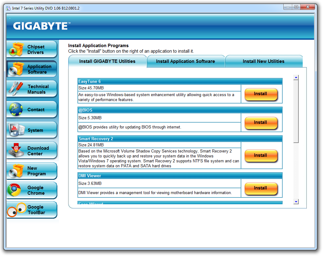
Anything under the ‘Install New Utilities’ tab is a one-by-one install process, such as 3D Power and 3TB Unlock. Annoyingly Gigabyte has not included the newer software on the CD, such as USB Blocker, TweakLauncher and CPU-Z GB Edition – this has to be downloaded via the website.
EasyTune6
The main part of the software is EasyTune6. One issue with ET6 is that it requires Flash to run, which is not normally part of my regular testing system install. I noticed that if I loaded ET6 after install and I was not connected to the internet, it would try and load a Flash installer. This installer would keep loading/unloading itself from memory and not do anything - only when I connected the internet did it silently do stuff in the background and load ET6. This is slightly odd behavior. Nevertheless when ET6 is finally opened, the first screen is the QuickBoost options:
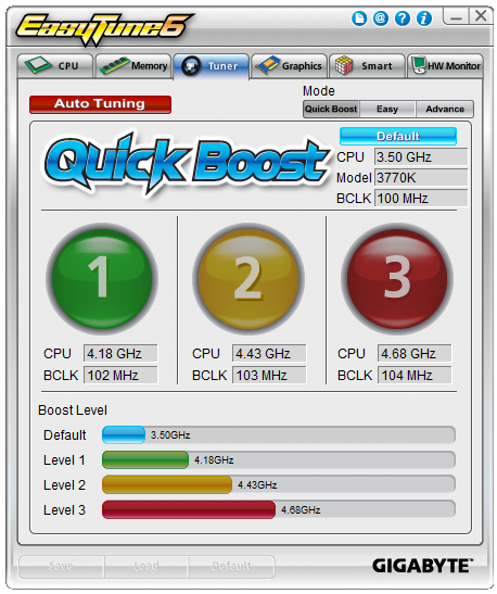
The software probes the system being used, and offers three different overclock profiles from fairly conservative (4.18 GHz) to mildly extreme (4.68 GHz) on our i7-3770K. The Auto Tuning option at the top is another way to go, which attempts to find the peak overclock of the system environment automatically through stress testing and consecutive improvements. We cover these in the Overclocking section later.
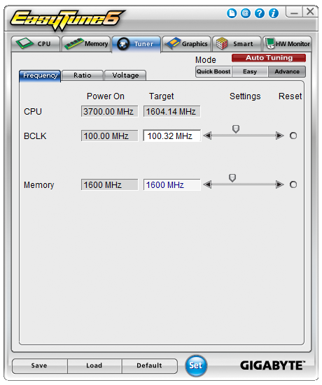
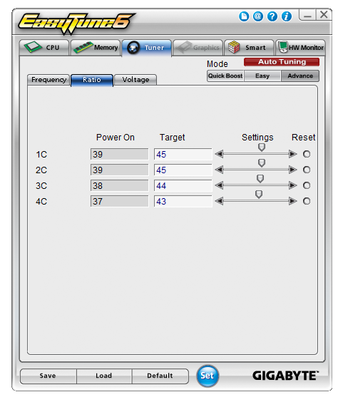
For manual overclocks, users can select ‘Easy’ of ‘Advance’ on the top right of the QuickBoost screen which opens up manual adjustment of frequencies and voltages:
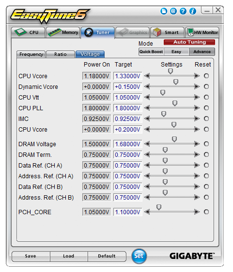
As the Z77X-UP7 has onboard OC buttons, most extreme overclockers will not even install ET6 and use the buttons instead. For when the system is in a case, ET6 offers the OS tools to perform the overclock, although some options may require a system reboot. Even then, the settings are applied after ET6 is loaded. This leads to some issues if the user requests a BIOS reset, which is often the regular way to deal with an overclock. As ET6 can load an OC profile on entering the OS, it essentially does not matter what the BIOS says. I had issues when ET6 would load an overclock after a BIOS reset, and then forcefully apply the previous BCLK adjustment via BIOS and the multiplier in the OS. Despite restoring the BIOS to defaults, the BCLK OC was still there, until I disabled ET6 loading any overclock profile. I have mentioned this to Gigabyte, to make ET6 take note if a BIOS reset was instigated and adjust appropriately / put up a message box asking to apply the previously saved overclock.
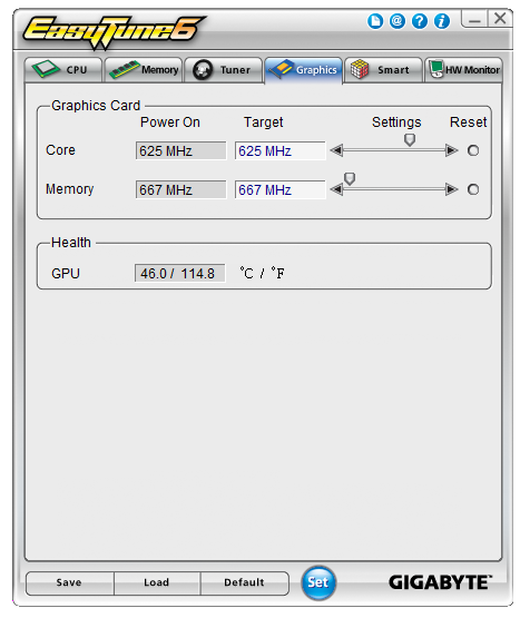
EasyTune6 also offers tabs to identify CPU and memory, like CPU-Z. The graphics tab allows users to adjust IGP or NVIDIA GPU clock speeds:
The HWMonitor tab is another oddity of the package – while monitoring tools as a whole are part of the motherboard ecosystem, this tab does everything the wrong way round. The tab with the graph of value vs. time initially shows voltages (which apart from VCore is not meant to change much), and the ‘Fan/Temp’ tab deals with when certain sensors get out of comfortable ranges. I would much rather have a graph of temperature and fan against time to begin with, followed by warnings when voltages go awry.
The final tab is the ‘Smart’ tab, where we can control the fan headers via the OS.
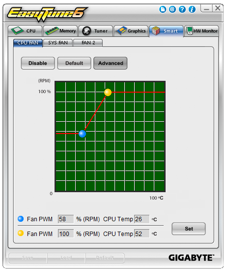
Despite the UP7 having a large number of fan headers, from ET6 we can only control 4 of them from three groups of settings. As mentioned in the BIOS section, the fan controls on Gigabyte boards a very basic, and in the OS we can only select a two point gradient for the fans with the top point of the gradient being at 100% power. Again, the OS system assumes that power applied to the fan is directly proportional to the RPM of the fan, which is completely wrong as mentioned before. In due course Gigabyte will update the fan ecosystem on their boards, and the tools to do this cannot come soon enough.
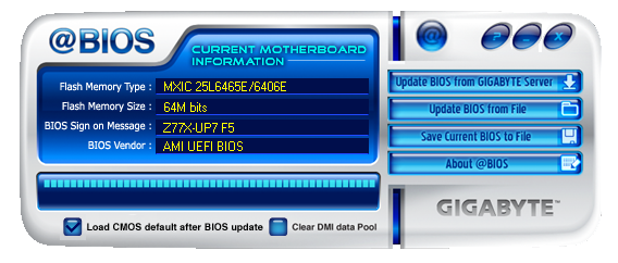
@BIOS
Almost all motherboard manufacturers now supply both OS and BIOS tools to update the operating system, with BIOS tools taking some time to filter down to the lower volume manufacturers. The @BIOS software from Gigabyte has been part of the software package for a number of years, allowing users to probe the online servers for new versions or dealing with BIOS files the user may have downloaded. I suspect more users are more comfortable updating the BIOS with software rather than in the BIOS itself, so it can be a relief for the user to have an easy-to-use system. The only thing missing is perhaps some integration with the rest of the software on the board, rather than dealing with multiple icons for all sorts of different things.
3D Power
One of the thorns in Gigabyte’s side, after launching 3D BIOS, was the launch of 3D Power. This software is designed to take advantage of the digital power options onboard, dealing with switching frequencies, load line calibration and phase response to requests for power.
However, the software itself is poorly written. Despite being written in Flash (most likely for visuals), it fails across the board in terms of user experience – the interface is slow, the animations are awkward, and there’s no option to reduce the whole thing to a menu system for power users. At a guess, the software must have been written by an intern – in an ecosystem where smoothness is a key part of the package, I am surprised Gigabyte has not called for it to be re-written by anyone more senior.
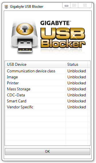
Gigabyte USB Blocker
At the request of some of Gigabyte’s business clients, USB Blocker was created – a niche software utility to enable/disable USB ports to various types of devices. This allows office or public computers to reject devices (such as USB keys) for fear of viruses or theft. Last time I reviewed the software, I laid out some concerns due to the software nature of the utility. Yes it can be password protected, but it does not apply in the BIOS, and can be uninstalled if the machine is booted in safe mode. The only way around this is to make USB Blocker part of the BIOS itself, however there might be issues dealing with different types of USB device on that front.
Gigabyte TweakLauncher (GBTL)
Overclockers rejoiced when Gigabyte TweakLauncher was created. Using ET6, as mentioned before, to deal with clock speeds and voltages was cumbersome and could result in system instability. When trying to go for those mammoth benchmark scores, stability is everything and GBTL is lightweight without any GUI to keep the extreme users happy. The main frequency and voltage options can be changed immediately here, along with all primary and secondary memory sub-timings. The Z77X-UP7 takes care of the CPU frequency settings portion of GBTL with the OC buttons, but extreme users will still find the program useful for everything else it does.
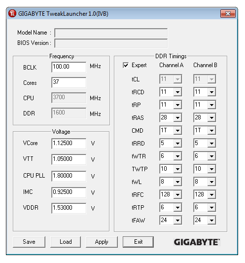
Like USB Blocker, GBTL is available as a download only.
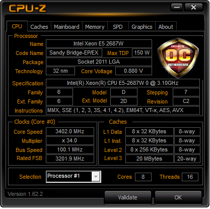
CPU-Z, Gigabyte OC Edition
As part of a growing trend, motherboard manufacturers are spending money on designing skins for CPU-Z, the CPU recognition tool used by overclockers to verify the hardware being used in screenshots of benchmark scores. Alongside the plain CPU-Z skin, there are downloads for the ASUS ROG, Gigabyte G1 series, and now the Gigabyte OC range, but the potential downside of these skins is that the main CPU-Z software is the most up-to-date, should any new significant change happen in the code base. The software is of course compatible for any system, including other manufacturers and sockets – for example, here on Sandy Bridge-E:


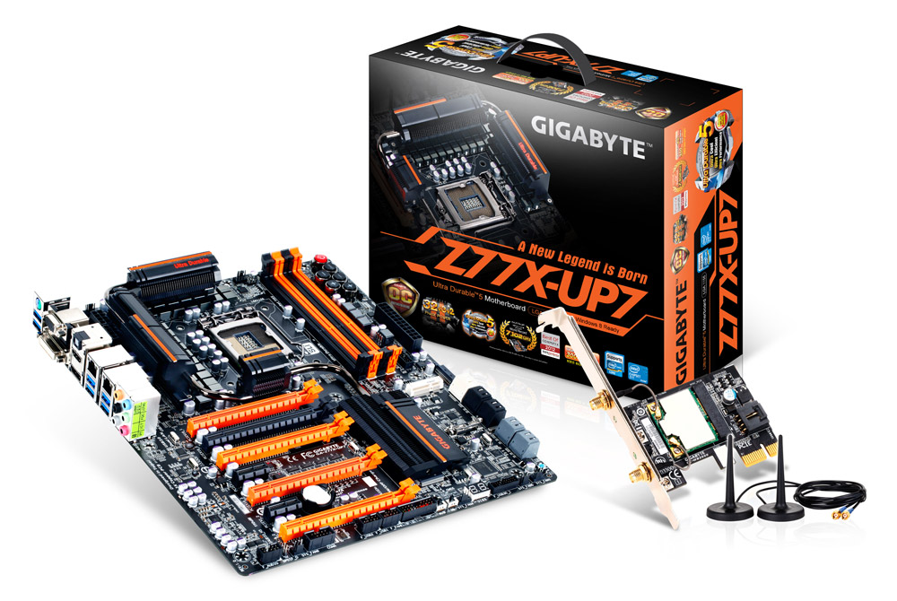
Gigabyte Z77X-UP7 In The Box
When spending $400 on a motherboard, even one aimed at a specific niche such as extreme overclockers, box contents are a vital part of the package to woo the user. As mentioned previously in the review, the Z77X-UP7 feels like an upgraded G1.Sniper 3, so I would not be too surprised if we see similar contents in the box. My hope for these themed packages is that something part of the package holds up to that theme, such as the ASRock Z77 OC Formula that comes with standoffs and an OC Formula labeled carry bag.
In our Gigabyte Z77X-UP7 package, we get:
Driver CD
WiFi Card CD
Motherboard Manual
WiFi Card Manual
Rear IO Shield
Dual slot Rigid 4-way SLI Bridge
Dual slot Rigid 3-way SLI Bridge
Quad slot flexi SLI Bridge
Quad slot flexi CrossFireX Bridge
GC-WB300D Dual Band 2x2 WiFi PCIe x1 Card supporting 802.11 a/b/g/n and Bluetooth 4.0
Dual Antenna for GC-WB300D
Eight SATA Cables
USB 3.0 Front Panel
eSATA Rear Panel with Molex Connectivity
Voltage Point Connectors
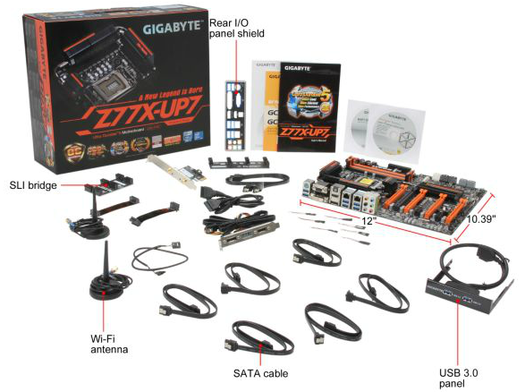
I am struggling to think of a package with this much kit included. Admittedly users wanting 4-way GPU action will have to forgo the WiFi card (as well as have a tight squeeze on the connectors at the bottom of the board). Overclockers will not care much about most of the package – the multi-GPU connectors and voltage point connectors being the priority here, but no doubt the inclusion of stand-offs (like the OC Formula) would have been appreciated. The only thing really missing is that essence of exclusivity – nothing in the package is solely specific to the UP7. Sometimes in motherboard packages we get posters or something similar, but no so here.
Gigabyte Z77X-UP7 Overclocking
Note: Ivy Bridge does not overclock like Sandy Bridge. For a detailed report on the effect of voltage on Ivy Bridge (and thus temperatures and power draw), please read Undervolting and Overclocking on Ivy Bridge.
Experience with Gigabyte Z77X-UP7
Overclocking on Gigabyte boards is a distinct mix when it comes to automatic and manual options. All the automatic overclock options are in the OS using EasyTune6, offering three different levels of fixed overclock and an automatic tuning option. Most users will head to the BIOS for manual overclocking outside of ET6 or GBTL, which as mentioned in the BIOS section of this review is an odd mish-mash of options around the place rather than menus focusing in on all the options of one particular element of overclocking. GBTL is a great little tool for extreme overclockers to eek out the last few MHz while in the OS.
For automatic overclocks, all of our options worked fine, although the Level 3 settings were extremely loose causing high temperatures due to voltage. The automatic tuning option did not fare too well, resulting in a mid range overclock that failed a memory test.
Manual overclocking was straight forward enough, although at every CPU speed we seemed to be one notch on the voltage higher than other boards. Temperatures were content up to 4.9 GHz on our setup as well.
For memory, our system did XMP on a 2x4 GB G.Skill DDR3-2666 11-13-13 1.65 V kit wonderfully, but failed to boot our memory kit with a simple notch up on the memory strap (2800 11-13-13) which both the ASRock Z77 OC Formula and MSI Z77 MPower did without issues. For kits in this range, it is advised to head over to this thread at HWBot to ask Gigabyte’s in house overclocker regarding what sub-timings should be changed. In terms of BCLK, our board rose to 109.6 MHz.
Methodology:
Our standard overclocking methodology is as follows. We select the automatic overclock options and test for stability with PovRay and OCCT to simulate high-end workloads. These stability tests aim to catch any immediate causes for memory or CPU errors.
For manual overclocks, based on the information gathered from previous testing, starts off at a nominal voltage and CPU multiplier, and the multiplier is increased until the stability tests are failed. The CPU voltage is increased gradually until the stability tests are passed, and the process repeated until the motherboard reduces the multiplier automatically (due to safety protocol) or the CPU temperature reaches a stupidly high level (100ºC+).
Automatic Overclock:
For automatic overclocking we used QuickBoost in EasyTune 6:
QuickBoost offers three levels of overclock and an auto tuning option. Our results were:
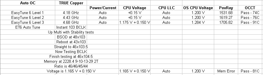
All three ET6 options were stable in our overclock testing, although the 4.68 GHz setting reached 91C during OCCT on an open test bed. The Auto Tuning option did its usual thing of going raising BCLK/Multiplier with stress testing, and finished with a staggered overclock (46x/46x/45x/44x) based on load with a CPU load voltage of 1.200 volts. This passed our CPU stress test (81C max) but failed our memory test.
Manual Overclock:
For the manual overclock testing, our usual procedure is to test the stock values, then dive in at 4.4 GHz at 1.100 volts as set in the BIOS. Based on previous overclocking scenarios, the following options were chosen throughout:
Power Limit: 500W
Current Limit: 300A
CPU Load Line Calibration: Turbo
If the settings were stable as per our testing, the multiplier is raised. If the settings fail, the voltage is raised by 0.025 V in the BIOS and tested again. Here are our results:
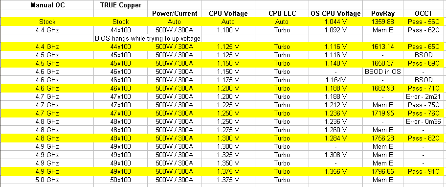
Compared to most of our Z77 testing, the UP7 does a good job - we hit 4.9 GHz within temperature limits, and 4.8 GHz with ease.
Many thanks to...
We must thank the following companies for kindly donating hardware for our test bed:
Thank you to OCZ for providing us with the 1250W Gold Power Supply and USB testing SSD
Thank you to Micron for providing us with the SATA SSD
Thank you to G.Skill for providing us with the memory kits
Thank you to ASUS for providing us the AMD GPUs and some IO Testing kit
Thank you to ECS for providing us the NVIDIA GPUs
Test Setup
| Test Setup | |
| Processor |
Intel Core i7-3770K Retail 4 Cores, 8 Threads, 3.5 GHz (3.9 GHz Turbo) |
| Motherboards |
ASRock Z77 Extreme4 ASRock Z77 Extreme6 ASRock Z77 Extreme9 ASRock Z77 OC Formula ASRock Fatal1ty Z77 Professional ASUS P8Z77-V Pro ASUS P8Z77-V Deluxe ASUS P8Z77-V Premium Biostar TZ77XE4 ECS Z77H2-AX EVGA Z77 FTW Gigabyte GA-Z77X-UD3H Gigabyte GA-Z77X-UD5H Gigabyte GA-Z77MX-D3H Gigabyte G1.Sniper 3 Gigabyte GA-Z77X-UP4 TH Gigabyte GA-Z77X-UP7 MSI Z77 MPower MSI Z77A-GD65 |
| Cooling | Thermalright TRUE Copper |
| Power Supply | OCZ 1250W Gold ZX Series |
| Memory |
GSkill RipjawsZ 4x4 GB DDR3-2400 9-11-11 Kit GSkill TridentX 2x4 GB DDR3-2666 11-13-13 Kit |
| Memory Settings | XMP (2400 9-11-11) |
| Video Cards |
ASUS HD7970 3GB ECS GTX 580 1536MB |
| Video Drivers |
Catalyst 12.3 NVIDIA Drivers 296.10 WHQL |
| Hard Drive | Micron RealSSD C300 256GB |
| Optical Drive | LG GH22NS50 |
| Case | Open Test Bed - CoolerMaster Lab V1.0 |
| Operating System | Windows 7 64-bit |
| USB 2/3 Testing | OCZ Vertex 3 240GB with SATA->USB Adaptor |
Power Consumption
Power consumption was tested on the system as a whole with a wall meter connected to the OCZ 1250W power supply, while in a dual 7970 GPU configuration. This power supply is Gold rated, and as I am in the UK on a 230-240 V supply, leads to ~75% efficiency > 50W, and 90%+ efficiency at 250W, which is suitable for both idle and multi-GPU loading. This method of power reading allows us to compare the power management of the UEFI and the board to supply components with power under load, and includes typical PSU losses due to efficiency. These are the real world values that consumers may expect from a typical system (minus the monitor) using this motherboard.
While this method for power measurement may not be ideal, and you feel these numbers are not representative due to the high wattage power supply being used (we use the same PSU to remain consistent over a series of reviews, and the fact that some boards on our test bed get tested with three or four high powered GPUs), the important point to take away is the relationship between the numbers. These boards are all under the same conditions, and thus the differences between them should be easy to spot.
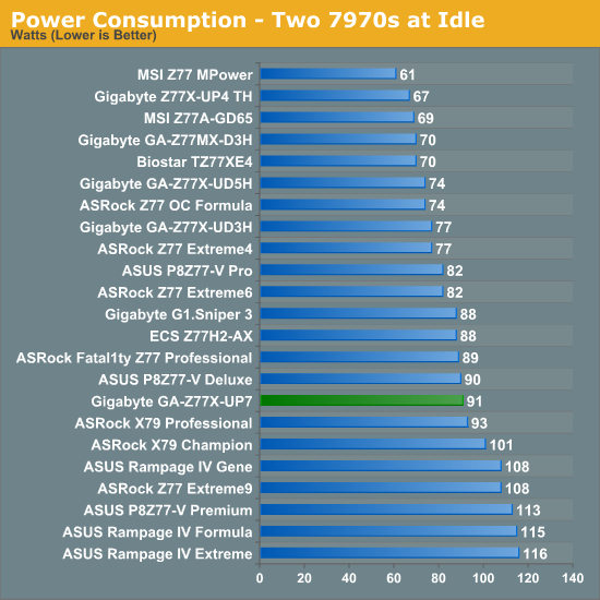
The Z77X-UP7 is stuck between a rock and a hard place on power usage. The IR3550s it uses are very efficient for power, but having 32 on the board (and 8 working at idle) causes a little more power usage than the other OC boards across our range of tests.
POST Time
Different motherboards have different POST sequences before an operating system is initialized. A lot of this is dependent on the board itself, and POST boot time is determined by the controllers on board (and the sequence of how those extras are organized). As part of our testing, we are now going to look at the POST Boot Time - this is the time from pressing the ON button on the computer to when Windows starts loading. (We discount Windows loading as it is highly variable given Windows specific features.) These results are subject to human error, so please allow +/- 1 second in these results.
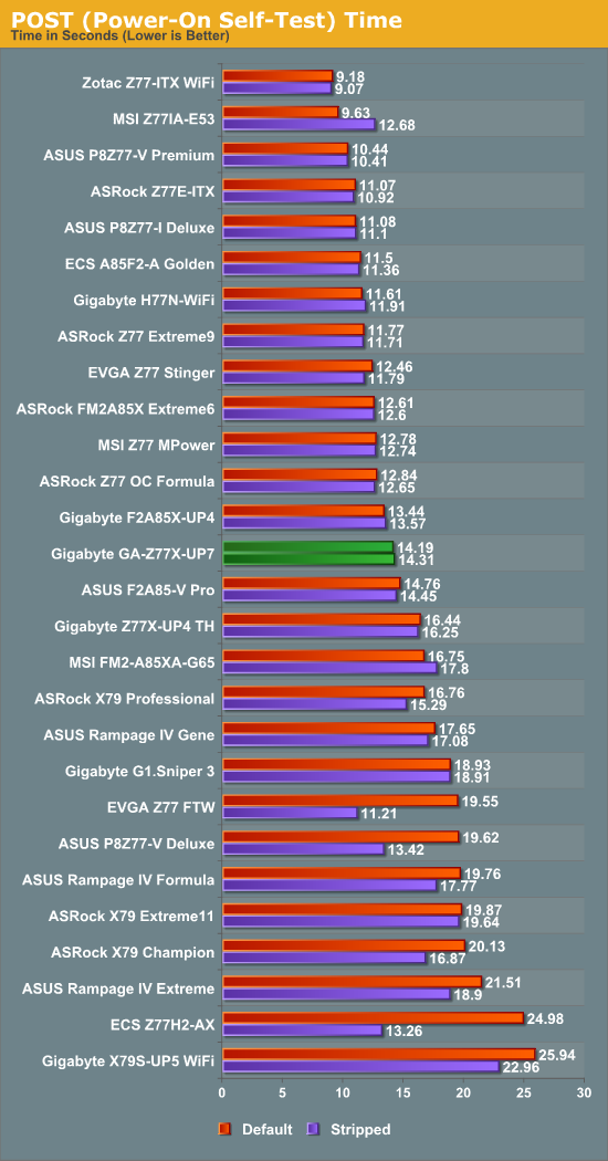
Boot time for the UP7 does not touch our artificial ‘sub-12 second’ ideal line, but at 14 seconds is the fasted Gigabyte Z77 board we have tested.
Rightmark Audio Analyzer 6.2.5
In part due to reader requests, we are pleased to include Rightmark Audio Analyzer results in our benchmark suite. The premise behind Rightmark:AA is to test the input and output of the audio system to determine noise levels, range, harmonic distortion, stereo crosstalk and so forth. Rightmark:AA should indicate how well the sound system is built and isolated from electrical interference (either internally or externally). For this test we connect the Line Out to the Line In using a short six inch 3.5mm to 3.5mm high-quality jack, turn the OS volume to 100%, and run the Rightmark default test suite at 16-bit with 48 kHz, 96 kHz and 192 kHz. We look specifically at the Dynamic Range of the audio codec used on board, as well as the Total Harmonic Distortion + Noise.
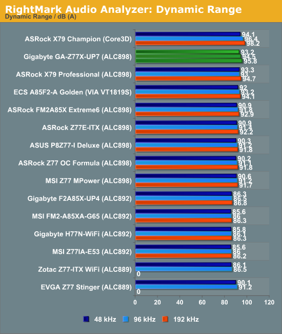
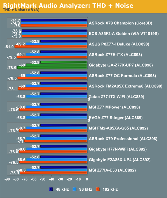
Our limited audio testing puts the ALC898 on the UP7 quite high up the table for dynamic range, but mid range for THD+N.
USB 3.0 Backup
For this benchmark, we run CrystalDiskMark to determine the ideal sequential read and write speeds for the USB port using our 240 GB OCZ Vertex3 SSD with a SATA 6 Gbps to USB 3.0 converter. Then we transfer a set size of files from the SSD to the USB drive using DiskBench, which monitors the time taken to transfer. The files transferred are a 1.52 GB set of 2867 files across 320 folders – 95% of these files are small typical website files, and the rest (90% of the size) are the videos used in the WinRAR test.

As the Gigabyte Z77X-UP7 has no rear USB 2.0 ports, we are only testing the USB 3.0 on offer. On the Rear IO we get two power from the Chipset, and four ports from a VIA controller. One header on board is from an Etron EJ168 controller, while the other onboard header completes the four from the Chipset.
Obviously the Intel USB 3.0 performs the best out of the options on the UP7, with the 2-port Etron controller matching the performance of other USB 3.0 implementations on the Z77 range. The VIA controller, as noted in previous reviews, is down on performance compared to others.
DPC Latency
Deferred Procedure Call latency is a way in which Windows handles interrupt servicing. In order to wait for a processor to acknowledge the request, the system will queue all interrupt requests by priority. Critical interrupts will be handled as soon as possible, whereas lesser priority requests, such as audio, will be further down the line. So if the audio device requires data, it will have to wait until the request is processed before the buffer is filled. If the device drivers of higher priority components in a system are poorly implemented, this can cause delays in request scheduling and process time, resulting in an empty audio buffer – this leads to characteristic audible pauses, pops and clicks. Having a bigger buffer and correctly implemented system drivers obviously helps in this regard. The DPC latency checker measures how much time is processing DPCs from driver invocation – the lower the value will result in better audio transfer at smaller buffer sizes. Results are measured in microseconds and taken as the peak latency while cycling through a series of short HD videos - under 500 microseconds usually gets the green light, but the lower the better.
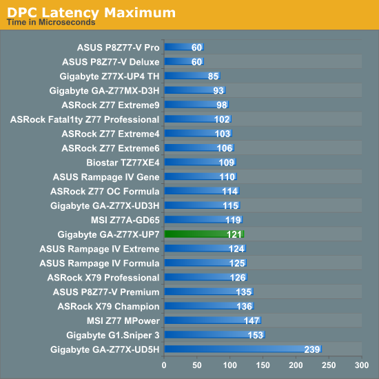
Now a regular feature of our testing, the DPC Latency of the Gigabyte Z77X-UP7 goes right under our 200 microsecond ideal line, and sits between the ASRock Z77 OC Formula and MSI Z77 MPower in testing.
MultiCore Turbo
Frequent readers of our motherboard reviews at AnandTech will have come across the term MultiCore Turbo. In a nutshell, when XMP is enabled, the motherboard adjusts the multiplier of the CPU to its highest Turbo bin for all loading – such that instead of 39x/39x/38x/37x for an i7-3770K, we get 39x across the board. This has obvious implications for multithreaded workload, which we explained and ‘asked the readers’ in a recent news item. Most motherboard from the major manufacturers (ASUS, Gigabyte, and now ASRock + MSI) has this option enabled by default when XMP is enabled, or a variation therein. It was originally designed to help certain users with software that had variable loading to stay stable, as well as speed them up to a small degree – the knock on effect is that for reviews, it shows up in the benchmarking when testing the out-of-the-box performance. For users intending to overclock, MCT is nothing to worry about.
For the Gigabyte Z77X-UP7, MultiCore Turbo is part of the BIOS used in testing.
3D Movement Algorithm Test
The algorithms in 3DPM employ both uniform random number generation or normal distribution random number generation, and vary in various amounts of trigonometric operations, conditional statements, generation and rejection, fused operations, etc. The benchmark runs through six algorithms for a specified number of particles and steps, and calculates the speed of each algorithm, then sums them all for a final score. This is an example of a real world situation that a computational scientist may find themselves in, rather than a pure synthetic benchmark. The benchmark is also parallel between particles simulated, and we test the single thread performance as well as the multi-threaded performance.
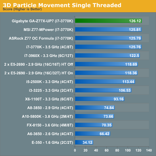
The single threaded version of 3DPM is more of a task in efficiency than anything else, and the UP7 hits the high notes, above the Z77 OC Formula and MPower, with ease.
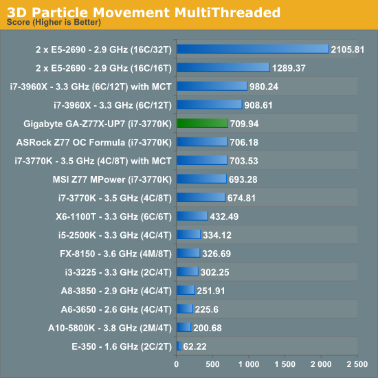
The Gigabyte Z77X-UP7 quite handsomely takes the 3DPM-MT crown out of all the Z77 motherboards using MCT, above the Z77 OC Formula. (The G1.Sniper 3 uses MCT-Plus, rising up to 4.0 GHz.)
WinRAR x64 3.93 - link
With 64-bit WinRAR, we compress the set of files used in the USB speed tests. WinRAR x64 3.93 attempts to use multithreading when possible, and provides as a good test for when a system has variable threaded load. If a system has multiple speeds to invoke at different loading, the switching between those speeds will determine how well the system will do.
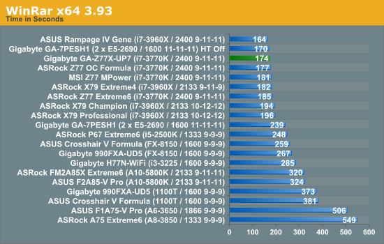
The efficiency shown in 3DPM-MT follows through to WinRAR, where the UP7 is two seconds behind the top Z77+MCT motherboard, and three seconds ahead of the ASRock Z77 OC Formula.
FastStone Image Viewer 4.2 - link
FastStone Image Viewer is a free piece of software I have been using for quite a few years now. It allows quick viewing of flat images, as well as resizing, changing color depth, adding simple text or simple filters. It also has a bulk image conversion tool, which we use here. The software currently operates only in single-thread mode, which should change in later versions of the software. For this test, we convert a series of 170 files, of various resolutions, dimensions and types (of a total size of 163MB), all to the .gif format of 640x480 dimensions.
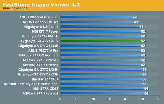
Across the range FastStone shows up very few variances due to its single-threaded runtime. The UP7 fits in the 52 second category, along with most Z77 boards. The high end ASUS boards are still kings for FastStone.
Xilisoft Video Converter
With XVC, users can convert any type of normal video to any compatible format for smartphones, tablets and other devices. By default, it uses all available threads on the system, and in the presence of appropriate graphics cards, can utilize CUDA for NVIDIA GPUs as well as AMD APP for AMD GPUs. For this test, we use a set of 32 HD videos, each lasting 30 seconds, and convert them from 1080p to an iPod H.264 video format using just the CPU. The time taken to convert these videos gives us our result.
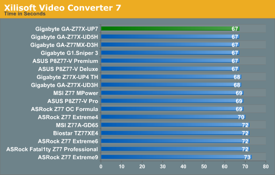
At full loading across all threads to convert video, and some memory overhead, all Z77 motherboards have fit in the 67-73 second window, albeit making ~9% from top to bottom. The UP7, like most Gigabyte boards, fits in the 67 second bracket, two seconds ahead of the ASRock Z77 OC Formula and MSI Z77 MPower.
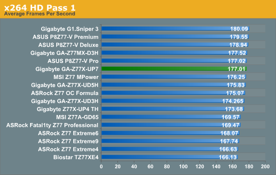
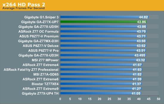
x264 HD Benchmark
The x264 HD Benchmark uses a common HD encoding tool to process an HD MPEG2 source at 1280x720 at 3963 Kbps. This test represents a standardized result which can be compared across other reviews, and is dependant on both CPU power and memory speed. The benchmark performs a 2-pass encode, and the results shown are the average of each pass performed four times.
Dealing with PLX 8747 Chips and PCIe Lane Layouts
The Z77 chipset specification allows Ivy Bridge CPUs to utilize the 16 PCIe 3.0 lanes in very specific layouts – x16, x8/x8, or x8/x4/x4. In order to do anything else (including 4-way), we have to put in a PCIe 3.0 switch – and the one in use on motherboards that want this functionality is the PLX 8747, which we covered in great detail back in August 2012. The upside of this chip is that for 8 or 16 lanes in, we get 32 lanes out, which can be distributed however the motherboard manufacturer wants. The downside of using this chip however is a small amount of overhead, causing a minor drop in frame rates. For the Gigabyte Z77X-UP7, we get the following configuration:
The UP7 involves a switch which allows the user to have access to a single PCIe 3.0 x16 slot without even touching the PLX chip. However the moment the user wants to add in another card, we can migrate to the orange slots via the PLX chip and maximize the bandwidth it offers. This gives five different configurations:
One card: x16 or x16 via PLX
Two card: x16/x16 via PLX
Three card: x8/x8/x16 via PLX
Four card: x8/x8/x8/x8
In this review I used the opportunity to look at our normal benchmark suite and see how much overhead the PLX chip actually affords to the motherboards that use it.
Metro2033
Metro2033 is a DX11 benchmark that challenges every system that tries to run it at any high-end settings. Developed by 4A Games and released in March 2010, we use the inbuilt DirectX 11 Frontline benchmark to test the hardware at 2560x1440 with full graphical settings. Results are given as the average frame rate from 4 runs.
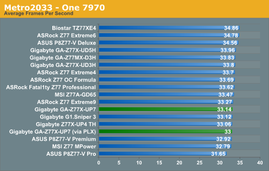
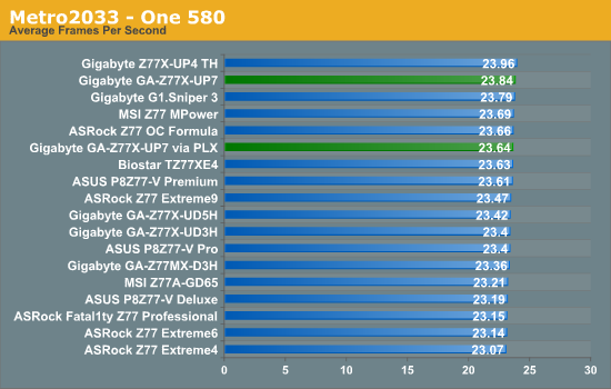
On the PLX front, the chip reduced the single AMD frame rate from 33.14 FPS to 33.00 FPS, a 0.415% decrease. On the NVIDIA side, it reduced our frame rate from 23.84 FPS to 23.64 FPS, a 0.839% decrease. Both of these are nothing much to shout about, especially given the previous NF200 on X58 was a decrease of ~2% performance. Compared to other Z77 motherboards, the UP7 takes advantage of the efficiency we saw in the CPU throughput benchmarks.
Dirt 3
Dirt 3 is a rallying video game and the third in the Dirt series of the Colin McRae Rally series, developed and published by Codemasters. Using the in game benchmark, Dirt 3 is run at 2560x1440 with Ultra graphical settings. Results are reported as the average frame rate across four runs.
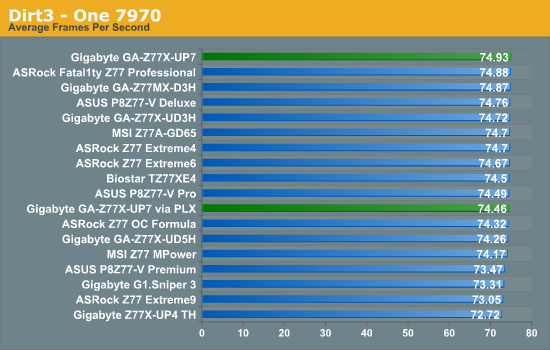
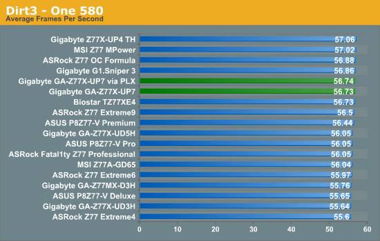
Again the PLX chip causes a minor hit to overall performance, as shown by the 1.97% drop on single card AMD (74.93 FPS to 73.46 FPS), but not so on NVIDIA (56.73-56.74 FPS) both with and without the PLX.
Other Benchmarks
As part of an upcoming update in our motherboard testing, we are moving towards newer drivers, and adding another couple of games to the test bed – Civilization V and Sleeping Dogs, both at 2560x1440 and all the graphical options turned right up. As we are not complete with this testing, we do not have any substantial tables to look through, though I do have Single GPU results on Catalyst 13.1 and NVIDIA 310.90 drivers for these games:
Civilization V:
- 86.43 FPS on HD7970
- 81.62 FPS on HD7970 via PLX
- 82.22 FPS on GTX580
- 80.40 FPS on GTX580 via PLX
Sleeping Dogs:
- 28.20 FPS on HD7970
- 27.98 FPS on HD7970 via PLX
- 16.10 FPS on GTX580
- 16.05 FPS on GTX580 via PLX
On all fronts the PLX chip causes a minor hit:
- Civ V: 5.57% on HD7970, 2.21% on GTX580
- Sleeping Dogs: 0.80% on HD7970, 0.31% on GTX580
Gigabyte Z77X-UP7 Conclusion
There are many industries where luxury products exist – cars, houses, holidays, and even a garlic press can be brushed up in aluminum, a $50 price tag, and be called ‘luxury’. Boutique builders will offer you a custom-built PC for many thousands of dollars, but are the internal components themselves anything special? We saw something of this ilk with the ASUS P8Z77-V Premium – a $450 motherboard built for functionality no matter direction you approached it from. But the Gigabyte Z77X-UP7 relies on one direction solely for its business, and hopes that extreme overclockers with $400 to spare will veer towards its orange glow.
Having a halo product in the market has advantages – advertise a top down strategy, and let those in the market know that you have the best product, and thus the products underneath that segment are worth considering. The halo product is often a flop in sales – not price competitive and unbalanced for R&D, but the halo effect kicking in should help the rest of the range. The Gigabyte Z77X-UP7 stands on top of its product stack, underneath the G1 Gaming series of boards and the channel SKUs. Recently it has been used to great affect, with Team.AU (an overclocking team sponsored by Gigabyte) taking a few world records.
The main feature of the Z77X-UP7 is the 32-phase IR3550 power delivery, which is advertised at being capable of delivering 2000W of power. We estimate this part of the board alone to be ~$125 of the asking price, and it truly is overkill. 32 phases, each at 60A, should be able to cope with 1920A of current, bearing in mind that that commercial power supplies never go that high, and the best Ivy Bridge CPUs hit 6.6 GHz for 3D loading at 1.9 volts, using up ~600W. This pulls out a number of ~320A, or 16.7% usage. While I often use the analogy of driving a 150mph car at 70mph vs. an 80mph car at 70mph to denote that having headroom is a good thing, 32 phases is obscenely overkill. It could have been reduced to 16 or 12 and still been sufficient for the most extreme of overclocks. It has been pointed out to me that ‘it’s there if you need it’, but no-one will ever need it – that is the issue.
Power delivery aside, if we discount that area of the motherboard, we are looking at what looks like a G1.Sniper 3 underneath. The pricing and in-box packages matches up rather well, with some minor deviations in feature placement – we liked the G1.Sniper 3 when we tested it at AnandTech, giving it a Bronze award for the price and performance it offered compared to other PLX enabled Z77 boards. The Z77X-UP7 is built for a different type of enthusiast, and this is one we have to consider both in terms of performance and utility.
The UP7 comes off well in most of our benchmark suite, beating many other MultiCore Turbo enabled boards for efficiency, especially in some of our computational benchmarks. As the board is designed to be overclocked most of the numbers in that section of the review will not apply, but more to our overclocking escapades. For users new to overclocking, the UP7 might be a little bit of a handful compared to some others – QuickBoost in EasyTune6 is conservative on the high end, giving us large temperatures for mid-range overclocks. Personally the software is not conducive to learning about overclocking, and the BIOS controls are an odd mash of separate menus and scattered options when ideally I would prefer a different layout. For the expert enthusiasts who are used to navigating these menus, this is of little consequence, and Gigabyte TweakLauncher is the perfect software companion alongside the onboard OC-Touch buttons.
But the general conclusion on the UP7 is going to be that we have a nice design at our fingertips, but a power delivery makes the product, and price, overkill. 12 phases would have suited 99.9% of overclockers (Ivy Bridge hitting 600W at extreme OC, so no need for 1000W let alone 2000W) and still get the efficiency benefit of IR3550. Even if you remove that and price the rest of the board at $250, it meets the G1.Sniper 3 at $280. Sniper has dual NIC including an Atheros Killer, but the UP7 has the single GPU aspect for it. UP7 has OC-Touch, Sniper has better audio, TPM and a PCI slot. Both have 4-way support, UP7 has more fan headers and separate BIOS switches, but the Sniper3 is technically faster at stock. Basically the UP7 is a souped up Sniper3 for overclocking - move some of the non-overclocker specific stuff off (Killer, audio, TPM, PCI) the Sniper, add the phases, a PCIe slot that bypasses the PLX chip, OC Touch, fan headers and Bob's your uncle.
Compared to the other OC motherboards we have tested, the Gigabyte is a tough sell over the ASRock Z77 OC Formula, because the ASRock competes on many different levels. If you need to go 4-way, out of the boards we have tested, the Gigabyte UP7 is the way to go. But for anything 2-way or less then the ASRock leaves a better taste in the mouth, particularly if: (a) anything breaks, (b) the board is going to be used for something other than extreme overclocking, and/or (c) the user is still learning about overclocking. The only other motherboard competing for 4-way extreme overclocking is the ASUS Maximus V Extreme, which runs $370 but is aimed towards gamers and general users as well, with Thunderbolt and built-in WiFi among other things.
If Gigabyte was going for more sales, from my perspective, if some of the IR3550s were removed and the system reduced to just over $300, it might get more takers, although the rebuttal is that the Halo Product of the range should be a no-holds barred affair. For many extreme overclockers, price is no object and the best will only be good enough – the Gigabyte Z77X-UP7 is a good contender for that spot for sure, but for everyone else it is a big ask to hand over $400.


